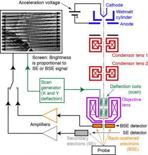
The SEM is composed of several primary operational systems:
Vacuum
A vacuum, typically 10-5 - 10-11 Torr, is required when using an electron beam because electrons will quickly disperse or scatter due to collisions with other molecules.
Electron beam generation - electron gun
The e-gun generates the primary electron beam at the top of the column. There are two types of beam emission to excite the electrons off the filament:
Thermal Emission:
Electrons are extracted from heated filaments by applying high electric potential between filament and anode:
-
Tungsten filaments that can be operated at lower vacuum (~ 10-4 Torr) with short life (~ 100 hr) and low electron emission inadequate for high resolution SEM;
-
LaB6 filaments that have a higher electron emission, better resolution and longer life (~ 2000 hr) but with high cost and a higher vacuum (~ 10-6 Torr) is needed.
Field Emission:
- Cold Field Emission (CFE ) has a sharp single crystal W tip mounted on a hairpin filament and a strong electric field (~ 107 V/m) is applied between tip and aperture anode to induce electron tunneling through the barrier at ambient temperature. The advantages are cool emission, much narrow beam width (~5 nm) and longer filament life. A high vacuum is needed (1<10-11 Torr) to keep W tip clean.
- Schottky Emission (SE) has similar setup as CFE but with the W tip coated with ZrO2 and heated (~ 1800 K) to facilitate electron emission and tip clean. SE has a higher source stability and low beam noise, high electron yields comparing to CFE.
E-beam Manipulation
This system consists of electromagnetic lenses and coils located in the microscope column and control the size, shape, and position of the electron beam on the specimen surface. The electromagnetic lenses are formed by passing electric current through copper wires to induce magnetic field.
Condenser Lens:
The condenser lens performs the spot size control by converging the cone of the electron beam to a spot below it, before the cone flares out again and is converged back again by the objective lens and down onto the sample.
Raster Coils (Deflection Coils)
The beam passes through two sets of magnetic scanning coils for beam scanning in both X and Y directions. The magnification is controlled by modulating scanned area, the smaller area the large magnification.
Objective Lens:
The objective lens focuses the beam into a spot on the sample. This is necessary to have an image in proper focus.
Signal Detection:
The interaction between primary e-beam and sample generates a multitude of signal types: back-scattered electrons (BSE), secondary electrons (SE), X-Rays, Auger electrons and Cathodoluminescence. The topographical information is obtained through BSE and SE signals.
Secondary Electrons (SE) Detector
SE detector magnetically attracts emitted secondary electrons by a low positive voltage applied to a ring around the detector (Faraday Cup). Upon entering the ring, the secondary electron is attracted and accelerated by a high positive voltage (~ 10 kV) on the scintillator. The secondary electrons hit the scintillator causing photons to be emitted. Photons emitted from the scintillator travel down the light pipe hitting the photomultiplier (PM).
SE imaging, being more surface sensitive due to short electron escape depth (~10 nm), has higher spatial resolution and provides mainly topographic information.
Back-scattered Electrons (BSE) Detector
BSE detector is similar to SE detector but without positive voltages applied. To maximize the detection of BE signals, the detector is positioned as close to the primary beam as possible without interfering with the primary beam.
BSE imaging has a lower spatial resolution due to longer electron escape length. However, as the BSE intensity is proportional to the mean atomic number of the atoms, the BSE imaging provide information on variations in sample composition.